¶ What is it?
Synapse PDM is an open-source automotive power distribution module designed for enthusiasts, motorsport competitors and vehicle builders who want a flexible, fully configurable electrical system.
The platform combines intelligent power distribution with mobile connectivity, GPS, SD card logging and an onboard IMU, providing a flexible platform for vehicle electrical control, monitoring and logging.
The project began during the restoration and EFI conversion of my Triumph Spitfire. As the electrical system grew to accommodate electronic fuel injection, additional fuel pumps, ignition control and engine management, it became clear that the original fuse box was no longer the right solution.
What started as a simple six-channel power distribution module intended to complement the factory wiring has evolved into a fourteen-channel system capable of managing an entire vehicle's electrical system, while adding advanced monitoring, logging and control capabilities.
Synapse PDM draws inspiration from established motorsport power distribution systems from manufacturers such as Haltech, Aim and Link. While those products represent the benchmark for professional motorsport electronics, Synapse PDM takes a different approach by providing an open-source, highly configurable platform that remains accessible to enthusiasts and independent vehicle builders.
Synapse PDM continues to evolve through ongoing development and real-world testing. The Technical Partner Programme has been established to enable closer collaboration with grassroots motorsport teams, helping to guide future development and validate the platform in demanding competition environments.
For discussion and updates, join the Facebook Group, Discord server or see my YouTube channel.
Units now available to purchase in my web store
¶ Features
- 14 Infineon PROFET BTS50025-1TEA high-side driver outputs up to 17A per channel.
- Configurable load current and channel diagnostics.
- Channel grouping for high-current outputs.
- 150Hz PWM or digital output
- Configurable retry attempts.
- 8 active-high digital inputs. Polarity protected, over-voltage protected and current limited.
- 8 configurable analogue/digital inputs with switchable pull-up or pull-down resistors. 12V tolerant, 5V analogue reference. Polarity protected, over-voltage protected and current limited. 12-bit resolution.
- CAN interface for channel control and status.
- SD card logging at 10Hz.
- LCD status screen.
- 9-DOF on-board IMU (from HW v1.8).
- SIM module with 4G data and GPS.
- Tracking and telemetry.
- Motion activated wake-up and tracking.
- Configuration, log download and monitoring via the multi-platform PC app. Windows, Linux & Mac OS.
- Low sleep power of ~1mA.
- Staged thermal shutdown protection.
- Cortex desktop application for live status monitoring, configuration save/load, log visualisation with GPS co-ordinate & parameter mapping and firmware updates.
- Custom bootloader supports in-place firmware updates with LCD status. Digital signature and SHA256 verified updates via Cortex.
PWM duty is voltage-compensated against a nominal battery voltage of 13.8V.
Some features aren't implemented. Check the GitHub repositories for info.
¶ Current State of Development
As of 2026, the Synapse PDM hardware is production-ready, with extensive functionality already implemented across the firmware and Cortex application platform.
Development remains active, with new features, enhancements and refinements continuing as the platform evolves.
See the GitHub pages for the firmware and configuration utility for progress.
The SynapsePDM firmware repository can be found here.
The SynapsePDM bootloader repository can be found here.
The Cortex software repository can be found here.
The hardware can be found on OSHWLab, here.
Enclosure CAD can be found here.
¶ Wiring Example
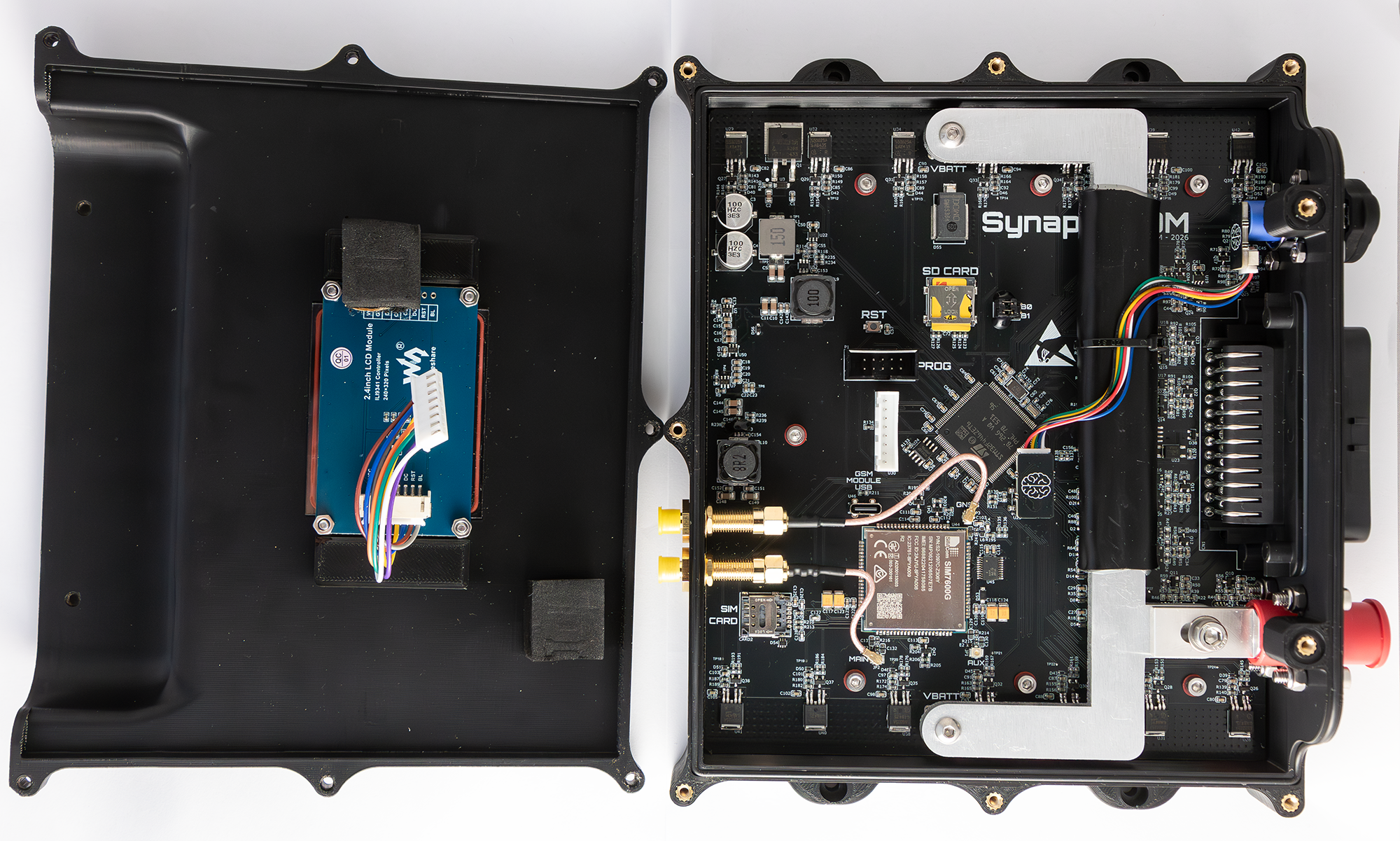
¶ Hardware
The 4-layer PCB measures 186mm x 160mm. Outer copper needs to be 2oz to effectively dissipate heat. The high-side drivers are fed by threaded terminals for high current capability. Seven drivers along each edge of the board with four layers and thermal vias to dissipate heat. Most of the other connections are made using the 35-way Ampseal connector.
On the board, you'll find a micro SD card socket, SIM card socket, GPS and mobile data U.FL antenna connectors, display header, programming header, external USB-C socket, debug USB-C socket for the SIM7900X module and the usual STM32 boot mode selection headers.
Input power is protected from over voltage (load dump) and reverse polarity.
Inputs are over voltage and under voltage protected as well as being current limited.
The CAN interface is protected from transients.
The connection to VBatt along the top row of drivers (U27) is also used to power the control electronics.
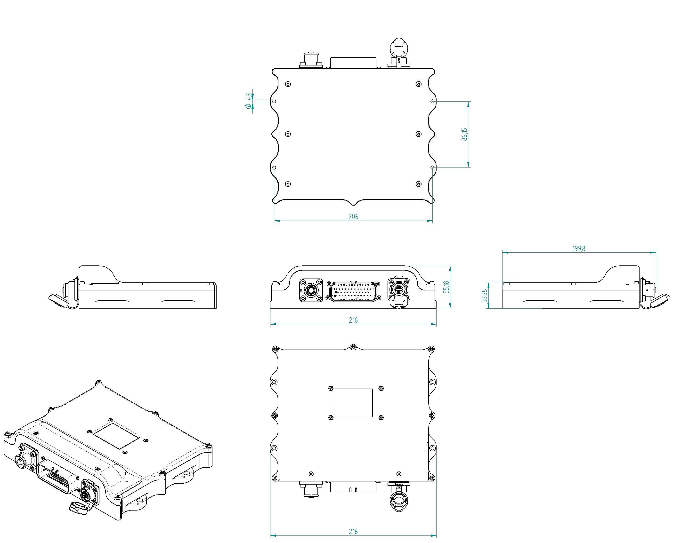
¶ Dimensions
Dimentions are in millimeters.
¶ Thermal Limits
¶ PCB
I selected the BTS50025-1TEA due to their extremely low on resistance. Worst case being 5mΩ. If we take a maximum single channel steady-state current of 20A and calculate power dissipation (I2R), we see a power dissipation of 2 watts per channel. Thermal resistance given in Infineon's datasheet of 22°C/W yeilds a temperature rise of 44°C. This of course, describes the thermal characteristics a single channel. Multiple adjacent channels at full load will enevitably see a greater temperature rise. They are rated to 150°C operating temperature so should withstand high currents even at relativley high ambient temperatures.
The current carrying traces and the connector are probably the limiting factors in maximum achievable current. The traces are 4mm wide. On 2oz copper, on a 4-layer board with internal ground planes at 20A, that gives a temperature rise of 42°C. 25A on the same trace gives a temperature rise of 70°C which is getting too close in an ambient environment that may be 40°C or more. This has been improved from v1.8 onwards where a 5mm aluminium heat spreader is bolted to the entire PCB.
Internal components are rated to a minimum of 85°C ambient operating temperature. System temperature is derived from the STM32 processor itself which has a maximum operating junction temperature of 105°C, 85°C ambient.
The PDM should be installed away from engine bay heat soak areas where possible.
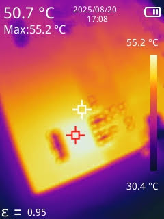
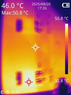
¶ Thermal Testing
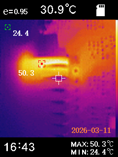
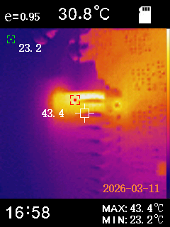
Below are some thermal images from my testing. A single channel loaded at 17A (left) and an adjacent pair loaded at 24A (12A each, right). Testing was done on a channel closest to the edge of the board which has the worst case copper area for dissipation. The board was mounted in the 3D printed enclosure with the 5mm aluminium heat spreader attached to the under side of the PCB using thermal tape.
The highest temperature rise was for the single 17A test, that channel saw a 25°C rise.
I have more thermal testing planned to fully load several adjacent channels, but looking at these initial results, I don't see any cause for concern.
¶ Gold vs. Tin Plated Connectors & Terminals
In both tests below, the tin plated 35-way PCB header is used (part number 776163-1). The gold plated header is part number 1-776163-1 and is specified on the most recent BOM.
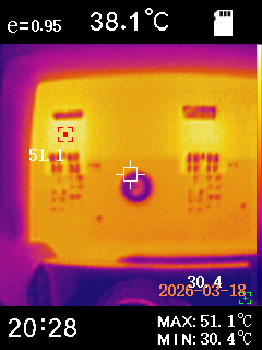
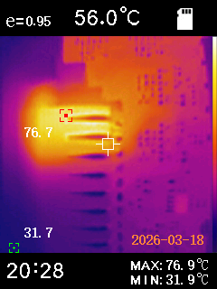
Each test was a single channel loaded to 15.5A and soaked for 10 minutes. First image shown is with tin plated crimp terminals, the second with gold plated terminals.
As you can see, simply by changing the terminal to the gold plated variant, decrease in temperature rise by 5.7°C is obtained.
Below are 4 adjacent channels with gold plated crimp terminals, loaded at 15.5A each and soaked for 10 minutes.
These temperatures are well within the operating temperature of 105°C for the tin plated PCB header and even more so for the gold plated header which is rated to 125°C. The surrounding parts are rated to 125°C or better.
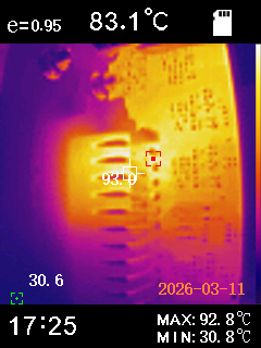
Loading 7 adjacent channels starts to get a bit close to limits. Again, 15.5A each, soaked for 10 minutes. This is quite an extreme scenario, however. 109A of the total system current limit of 150A loaded entirely on one set of drivers and adjacent pins but it does show that some consideration is required to distribute the required load.
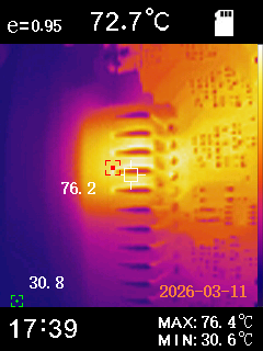
PCB v1.8 supports the use of a 5mm heat spreader that attaches to the underside of the PCB and is in contact with the whole PCB area. The images below are for four adjacent channels loaded at 15.5A each and run for 20 minutes. Notice the max. driver temperature of 51.1°C. The connector running at 76.7°C but still well below the 105°C operating temperature. The PCB itself also much cooler.
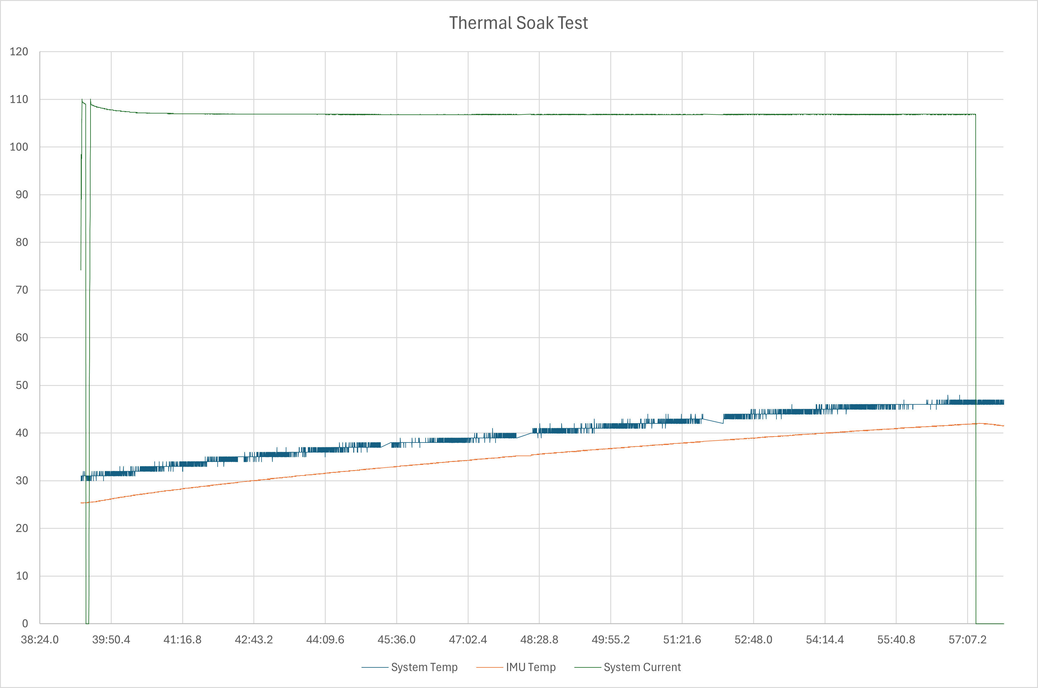
The soak test below shows ~107A over a 20 minute period with the system and IMU temperature traces. The maximum was 47°C which was measured in the processor, which represents a 23°C rise over the ambient temperature in the room at the time (24°C).
¶ Connectors
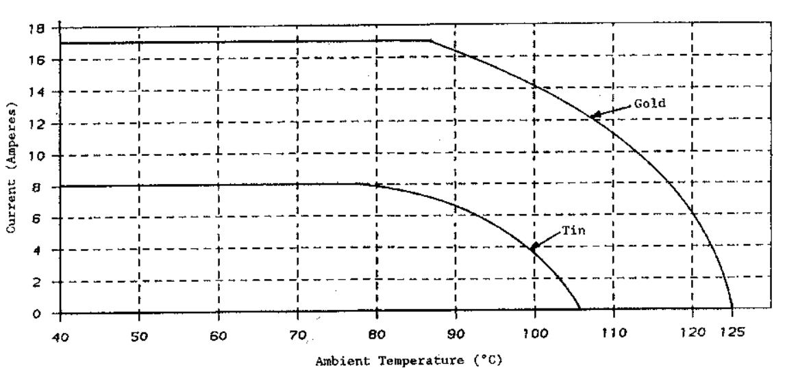
The Amphenol connector is rated to 17A per pin and only a certain subset of pins can be loaded according to their datasheet as seen in the derating table below. Use of the gold contacts is also a requirement for these ratings.
Connector - 2454990-1. Gold plated terminals - 770520-3.
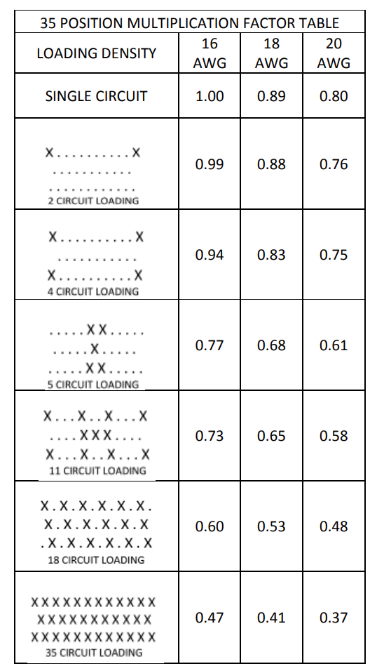
It is worth pointing out that this derating table applies to the connector at an ambient operating temperature of about 85°C at which point they are derated from there up to 125°C for the gold plated pins (see chart below). In practice, loading multiple pins at 17A outside of this pattern is probably going to be fine.
Given these limits, I decided to hard-code the firmware with a 17A limit. Channels can be paired for this reason, to allow control of high-current devices.
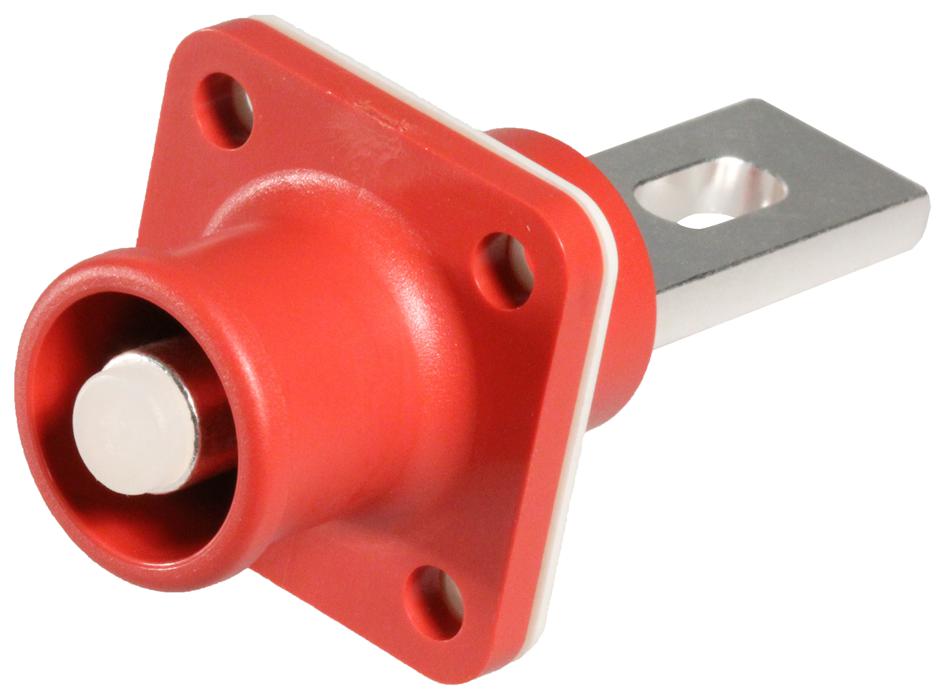
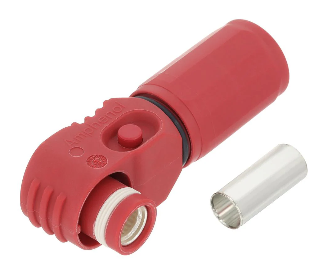
The main power is supplied via an Amphenol SurLok connector. These robust and IP rated connectors are ideal for this applicaton. The one I fitted can supply 150A with a 35mm2 cable. Cable connector part number SLPPB35BSR, panel socket part number SLPRBBPSR.
¶ 35-way Connector Pinout
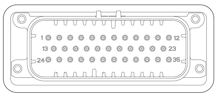
| Ampseal pin | Function | Ampseal pin | Function | Ampseal pin | Function |
|---|---|---|---|---|---|
| 1 | Output 3 | 13 | Output 2 | 24 | Output 1 |
| 2 | Output 4 | 14 | Digital in 1 | 25 | Analogue in 1 |
| 3 | Output 5 | 15 | Digital in 2 | 26 | Analogue in 2 |
| 4 | Output 6 | 16 | Digital in 3 | 27 | Analogue in 3 |
| 5 | Output 7 | 17 | Digital in 4 | 28 | Analogue in 4 |
| 6 | CAN L | 18 | Digital in 5 | 29 | Analogue in 5 |
| 7 | CAN H | 19 | Digital in 6 | 30 | Analogue in 6 |
| 8 | Output 8 | 20 | Digital in 7 | 31 | Analogue in 7 |
| 9 | Output 9 | 21 | Digital in 8 | 32 | Analogue in 8 |
| 10 | Output 10 | 22 | Igntion | 33 | 5V Reference |
| 11 | Output 11 | 23 | Output 13 | 34 | Ground |
| 12 | Output 12 | - | - | 35 | Output 14 |
¶ Enclosure
The enclosure is designed to be 3D printed. Originally, I maintained a CNC machined variant but this isn't cost effective. The current enclosure can easily be adapted to a CNC machined version.
I recommend 3D printing the enclosure from ASA or similar which has good impact and temperature resistance.
¶ PCB Power Stage Design
Most peripherals are turned off when the PDM goes into sleep mode to save power before the processor goes into sleep mode by means of turning off the switched 5V and 3.3V rails.
The 3.8V SIM module regulator is tuned off via the enable pin in hardware v1.8 onwards.
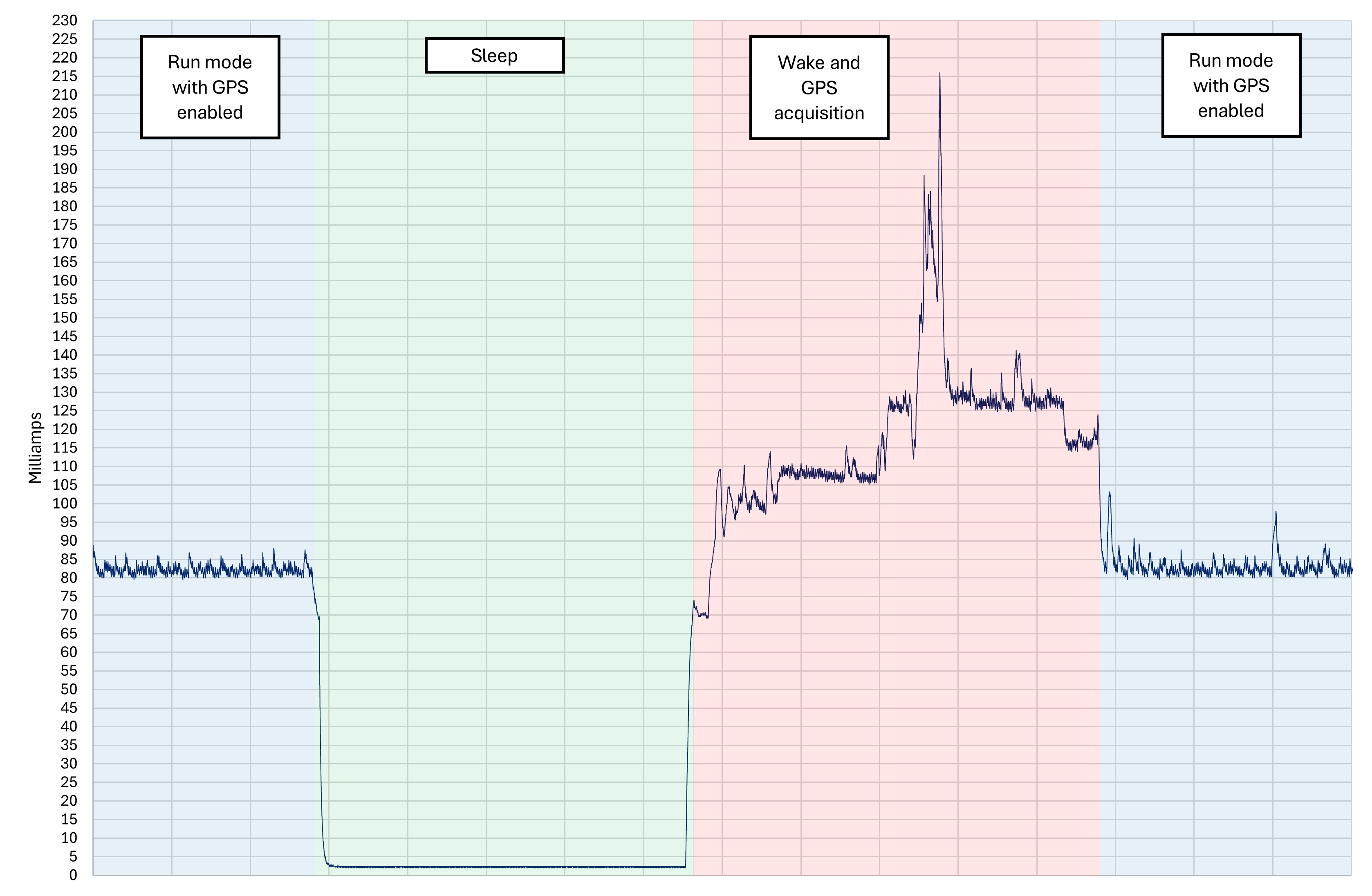
¶ Current Consumption
Current consumption in normal operating (no outputs on) with all peripherals running and GPS fix is ~85mA. Sleep current is about 1mA from FW v0.9.
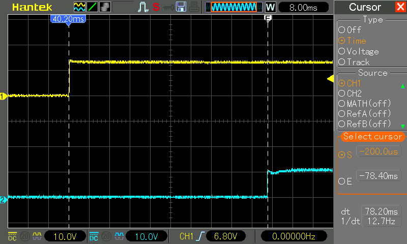
¶ Boot Time
The scope trace below shows ignition on (yellow) and an output (blue) where its input is already high on wake. Average time to output high on waking from sleep is 80ms.
Checking inputs and raising outputs are some of the first functions called when the system wakes. Other functions such as updating the display come after this.
¶ Firmware
The firmware is written using PlatformIO and the STM32 Arduino core targetting the STM32F446ZET6. Functions are called at different intervals depending on priority.
¶ Bootloader & Firmware Updates
As of firmware v0.8, the controller supports a custom SD bootloader. The bootloader can flash the application space from a binary on the SD card whilst showing erase and download status on the LCD. This is there to facilitate updates from Cortex or, in the future, OTA updates.
The firmware verifies the update from Cortex by comparing the hash with the downloaded SHA256 and verifies that the firmware is signed before proceeding.
Advanced users can still utilise the SD bootloader simply by loading a firmware binary named synapse.bin on the SD card and booting the controller. The bootloader automatically looks for this file and flashes it to application space if it will fit. Once download is complete, the flashed binary is renamed to synapse.bak to prevent unwated update cycles.
EEPROM is retained between updates on the external EEPROM chip.
¶ Outputs
Outputs are configured as either digital or PWM. PWM frequency is fixed at 150Hz. This is a limitation of the Infineon HSD and thermal management but is high enough frequency to run brightness control for lighting, speed control or to allow for soft-starting accessories. PWM control is acheived through DMA register manipulation. This allows for accurate timing with minimal CPU load.
¶ Digital Inputs
Digital inputs are quite basic, they are just active high, currently. Future plans would to allow these to be used as active high or low subject to further testing.
¶ Analogue Inputs
Analogue inputs have several configurable properties. Internal pull-up or pull-down resistors can be configured, the input can behave as a digital input or an analogue input. Analogue input types supported are raw voltage, passive, active or NTC thermistor. 2 or 3 point calibration is supported for linear or curve fitting active or passive sensors. Different units can be selected to make scaling and threshold adjustments more intuitive as well as log readability.
Ensure inputs are ignition-switched to prevent excessive current draw when the PDM is in sleep.
¶ GPS
GPS is sampled at 1Hz. A plausibility check takes place on co-ordinates and speed to filter out bad GPS fixes. GPS updates are given priority over all other GSM/GPS module commands.
¶ Protection Features
Outputs have several protection features.
¶ Under Current
Under current is the lower current thrshold for open-circuit detection. Should an output be active but the current is below this threshold, the output will be disabled with an open-circuit fault.
¶ Over Current
Over current threshold is used for detecting over current and short circuit events. Exceeding this value will either trigger retries if they are configured, or an over current fault, disabling the channel.
¶ Over Temperature
The BTS50025-1TEA high-side drivers have internal over-temperature protection. Temperature of the PDM is monitored in three places, the SIM/GPS module, the main processor and the IMU. This gives an overview of the temperature of the controller. A device type is assigned to each channel. Channels enter a staged shut down depending on system temperature, starting with the lowest priority channels.
¶ Inrush Delay
Inrush delay can be configured up to 2 seconds. This looks to the configured inrush current limit for the configured duration to determine a fault condition. This is inteded for use with accessories such as cooling fans that will draw many times their steady-state current at power on. The maximum inrush current threshold for a single channel is 50 amps. Beyond this, channels will need to be paired.
¶ Soft Start
Soft start can be configured up to 5 seconds. This uses PWM to ramp up the duty for the configured channel over the configured period. For a digital channel, this ramp concludes at 100% duty, For a PWM channel, this ramp concludes at that channel's configured PWM duty at the time of enable.
¶ Retry Attempts
Retry attempts can also be configured. The retry interval is approximately 150ms. This allows the PDM to make several attempts at activating an output with an over current fault before the number of retries is reached and the output is disabled a fault.
¶ Channel Grouping
Outputs can be grouped simply by assigning the same input to multiple channels. The current limits applied to each channel can therefore be summed for the total output current available. Generally, current sharing is reasonable between channels, but thermal factors and part-to-part on resistance prevent current from being distributed evenly. Expect to see some channels bearing more current than others and adjust limits accordingly. In the case of approaching the current limit across multiple channels, it may be neccessary to add an additional channel to that group to reduce the current load for each channel.
Bear in mind that if one channel in a group fails, the rest of the channels in that group will try and take the load. So long as limits are set appropriately, those channels will correctly fault also. The PDM will protect iteself, it's the wiring you need to consider.
Faults are reset the next time the associated input transitions from inactive to active.
¶ Error codes
The display shows an error code in the format "EXXXX". This is a 16-bit hex value. See the table below for individual bit stats or this page for decoding errors.
| Bit position | Fault |
|---|---|
| 0 | Over current (system level) |
| 1 | Over temperature |
| 2 | Under voltage |
| 3 | EEPROM CRC check failed |
| 4 | SD card error |
| 5 | PC comms checksum error |
| 6 | GPS error or no fix if enabled |
| 7 | Temperature warning |
¶ Data Logging
Data logging is always enabled as long as the date and time are set. All channel and sytem parameters are logged at 10Hz. 10 log files are retained and store one hour of data in each file. Filenames are in the format, YYYY-MM-DD_HH-MM-SS.csv which represents the date and time the file was created.
Multiple runs of the vehicle will potentially be stored in one file if they are under an hour. This ensures that there is always 10 hours of logged activity across 10 files.
¶ Date & Time
Date and time are obtained from GPS or can be set manually from Cortex.
¶ Sleep Mode & Power Management
The CPU shuts off all uneccessary peripherals & power rails and enters sleep mode when the ignition input goes low. Only the CPU itself and the IMU are kept powered during sleep. Testing shows a sleep current of approximately 1mA from FW v0.9.
The system exits sleep mode either by interrupt from the IMU (vehicle movement) or via the ignition input.
¶ IMU Wake Up
In sleep the IMU is armed to trigger an interrupt on any movement. This wakes the processor. A configurable timeout is set in system options. Wakes during this period are ignored. This is to account for occupants moving in the car after igntion off, doors closing etc. Upon waking after this period has elapsed, the system checks the ignition input state amd monitors movement for the configured period of time. If no movement or ignition is detected in that time, the system goes back to sleep. If movement persists, other actions can be taken such as reporting to a web service with GPS co-ordinates.
¶ Telemetry and Security
Currently there is no implementation for telemetry reporting or a security system as such. I envisage using something like ThingsBoard to implement telemetry & GPS tracking using MQQT. Security could be done by securing the PDM via an encrypted CAN message from a CAN based NFC module or similar.
¶ CAN Bus
Here is a comprehensive specification for the CAN messages and their IDs. Message IDs are shown here as firmware defaults, these are configurable through Cortex.
I recommend using Kvaser CAN database editor which is free. Download the CAN database for Synapse PDM in the SynapsePDM firmware repository.
Configuration changes over CAN are checked for differences with stored EEPROM parameters, if there is a change, a timer is set. If no more configuration changes occur within 5 seconds or ignition off (whichever comes soonest), the controller saves those changes to EEPROM. This prevents multiple unnecessary writes to EEPROM.
¶ Software
Written in AvaloniaUI for C#.NET, Cortex is the configuration utility for SynapsePDM which uses the USB interface/virtual COM port of the STM32.
The utility allows you to connect and configure the controller.
Read the user manual, here.
¶ License
SynapsePDM hardware is licensed under CERN-OHL-S v2. SynapsePDM firmware and the Cortex application are licensed under the GNU GPL 3.0.
¶ Disclaimer
This device is intended for MOTORSPORT, OFF-ROAD, AND EXPERIMENTAL USE ONLY.
DO NOT use this device in any vehicle operated on public roads.
This product is experimental, unverified, and may contain defects. By using this product, you assume all risks. The authors and contributors disclaim all warranties and are not liable for any damages arising from use of this product.
Please download and read the full disclaimer.