Welcome to the Cortex user manual. Cortex is written in C#.NET with Avalonia UI.
¶ Features
- System, CAN bus, output and input configuration
- Firmware update utility
- Live status monitoring
- Log download and visualisation tools
- Save and load configurations
- Linux and Windows support
¶ Installation
Releases are published on GitHub.
Windows - Simply download the release from GitHub, run the setup.exe installer.
Linux - Download the .tar.gz from the release on GitHub, extract to a folder of your choice.
- Mark the application as executable with chmod +x cortex
- Run with ./cortex
You may need to add your user to the dialout user group to access the serial port. This is done with sudo usermod -aG dialout username.
¶ Connect Tab
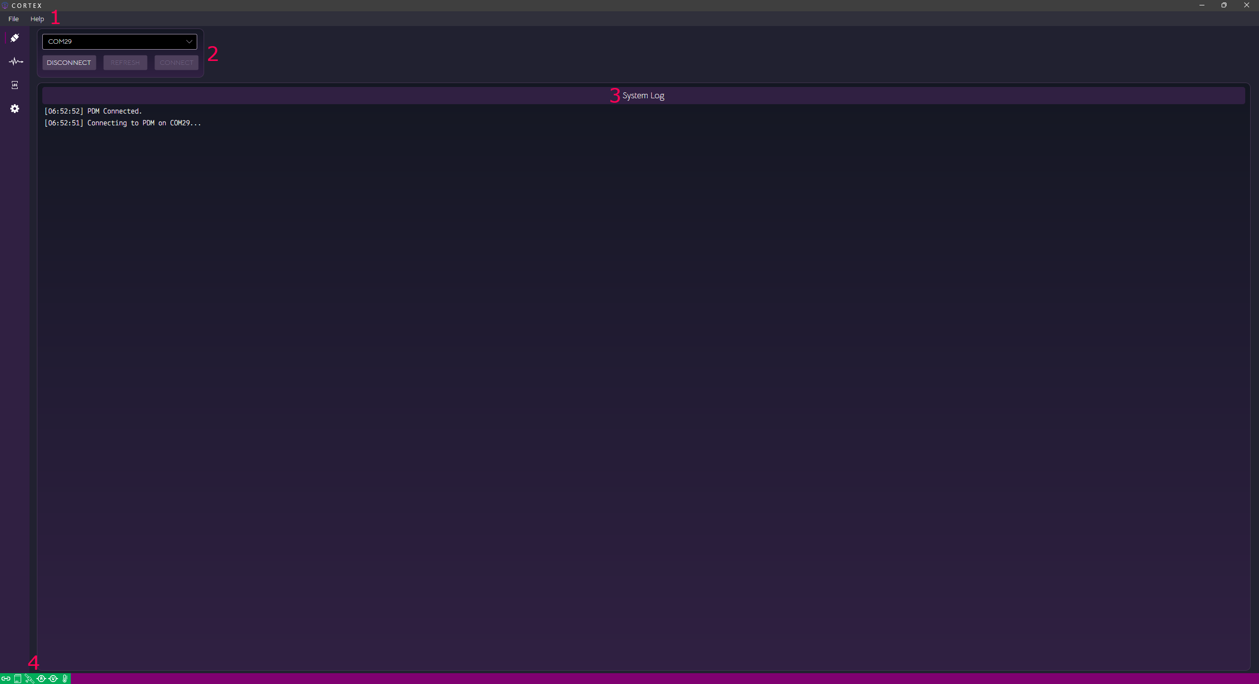
¶ 1. Menus
The file menu allows you to save and load configurations locally. It's good practice to save your configuration occasionally as a backup. Configurations can be loaded and sent to the controller.
¶ 2. Refresh, cancel and connect buttons
Here you see a list of serial ports available and buttons to disconnect, refresh the list of ports or connect to the controller.
¶ 3. System status log
This shows events that occured in Cortex while the PDM was connected. Newest events appear at the top of this list.
¶ 4. Status icons
From left to right, connection status, SD log status, GPS status, system current status, system voltage status, system temperature status. Geen = healthy, red = fault.
¶ Live Status Tab
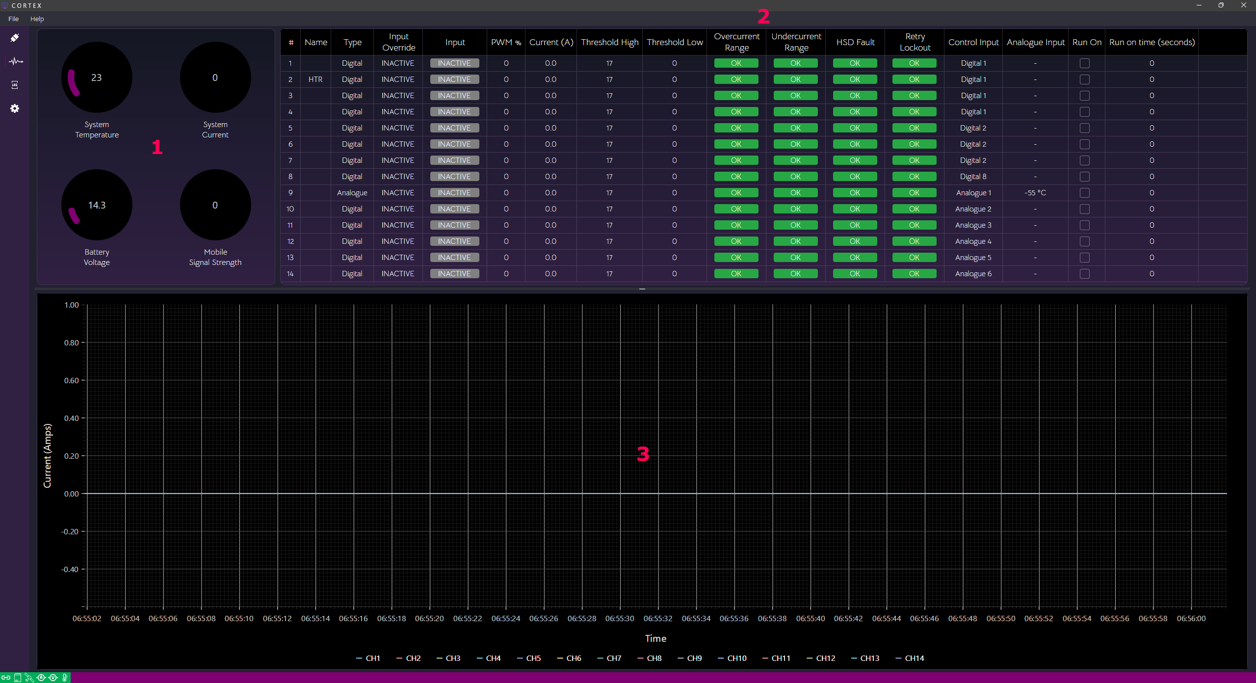
¶ 1. System metrics
This area displays live system temperature, system current, battery voltage and mobile signal strength (bars).
¶ 2. Channel status
Live channel status is displayed here as well as analogue values in the configured units.
Here you can manually override an ouput by clicking and holding "Inactive" in the Input Override column for the channel you want to override. The channel will still adhere to any current limits that have been configured. To disable override, click the cell for that channel again once.
Override is also reset when Cortex is disconnected, or the PDM goes into standby or power cycles.
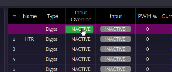
Use the override feature with caution!
¶ 3. Live channel current
The live chart shows a rolling minute of live current status for all channels.
¶ Log Tab
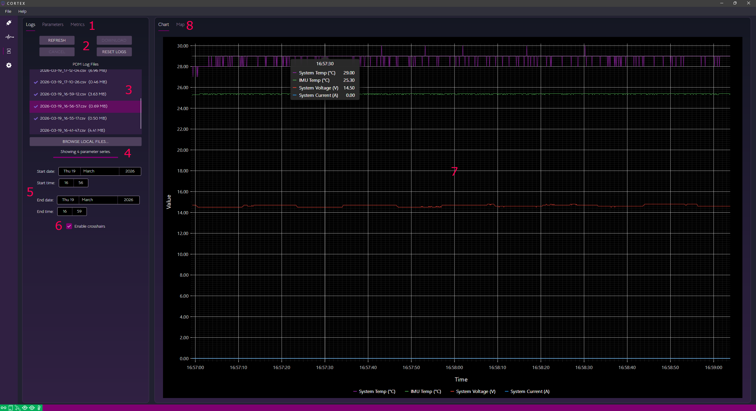
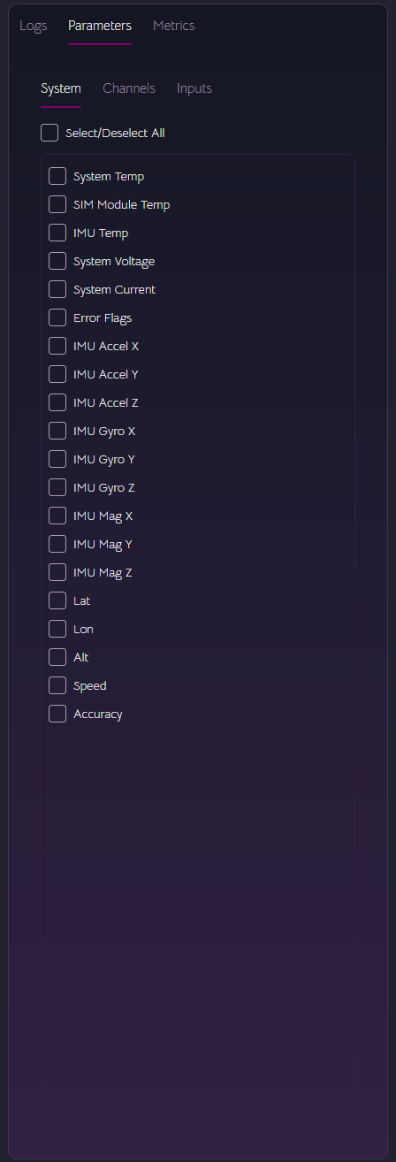
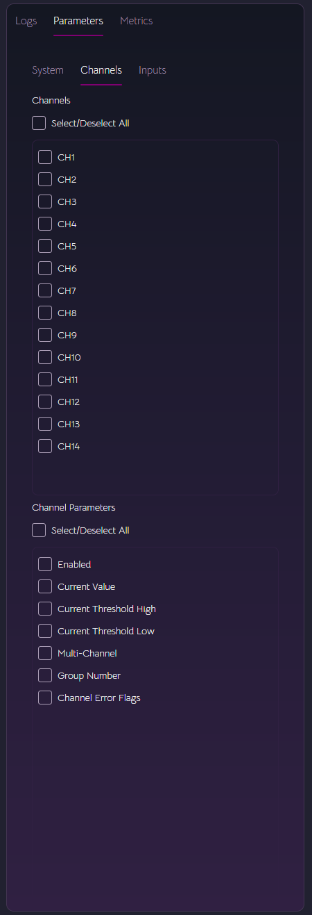
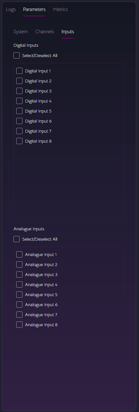
¶ 1. Log, Parameters, Metrics
Once a log is loaded, use the parameters tab to select the parameters to view:
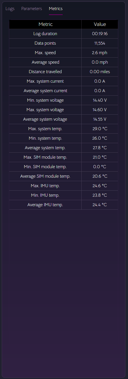
The loaded log file will populate the log metrics table:
¶ 2. Log commands
This refreshes the list of currently available logs on the controller. A maximum of 10 logs are kept on the controller. Clicking reset will delete all the stored logs and start a new one.
Select a log in the list and click download to transfer it from the PDM to your local drive. In Windows, these are stored in Documents\Synapse PDM Logs.
¶ 3. Log list
This is a list of logs currently available on the PDM. The logs with a tick next to them have aleady been downloaded and found on disk. Clicking browse alows you to load a log from a location of your choice. The log must be in the correct format to be read into the software.
¶ 4. Status
Log download progress and status. Log download times will vary depending on how many channels are currently enabled. The controller has to make more calculations and readings with more channels enabled.
¶ 5. Date & time range
Start and end date and times for the chart and map display.
¶ 6. Enable crosshairs
Enable crosshairs on the chart.
¶ 7. Chart
The chart supports zooming using the scroll wheel and panning with click and drag.
¶ 7. Map
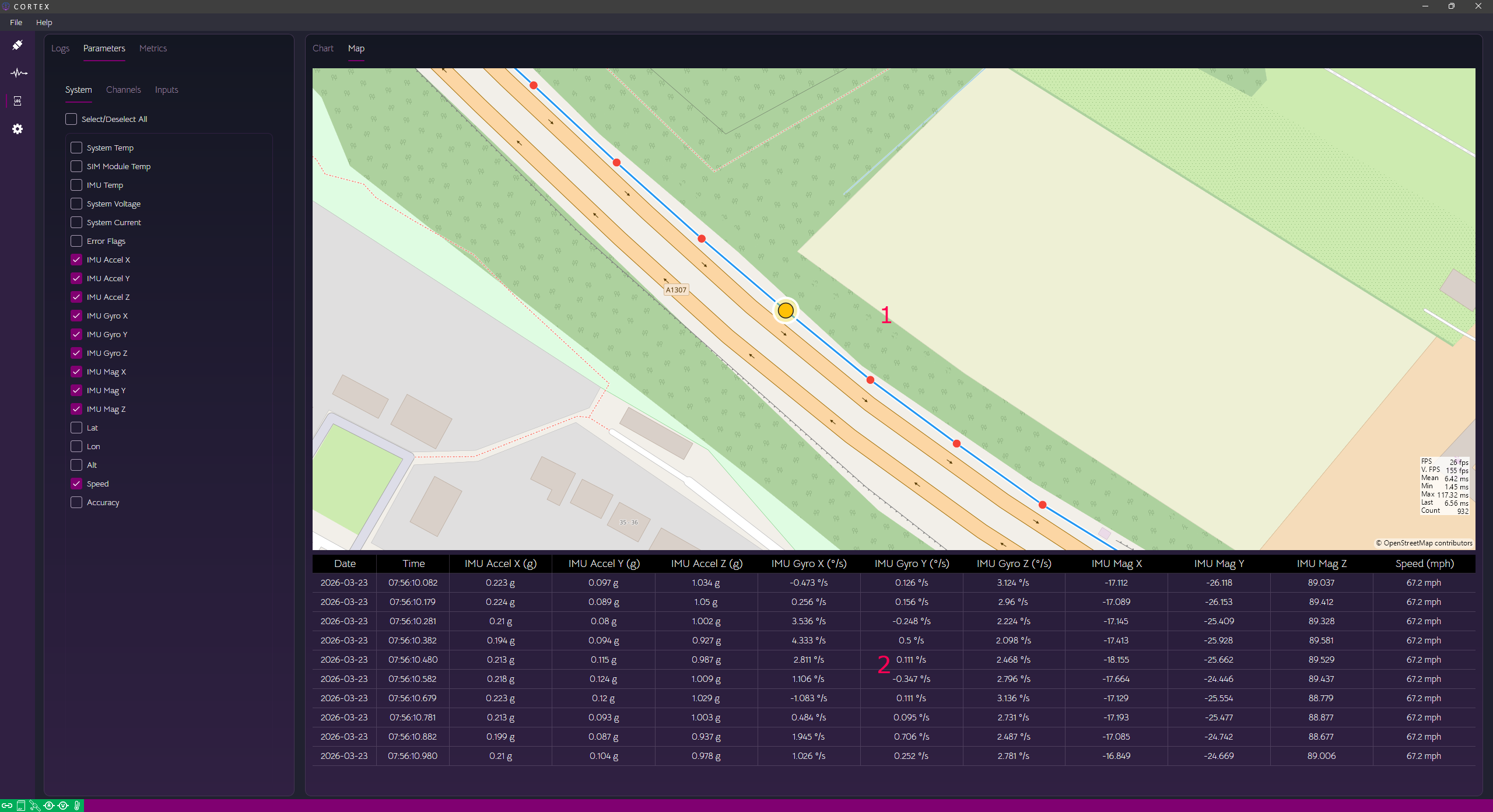
- The map view shows each GPS co-ordinate recorded. GPS is recorded at 1Hz.
- All other data is recorded at 10Hz. For each GPS point, 10 data points for the selected parameters will show in this grid.
¶ Settings Tab
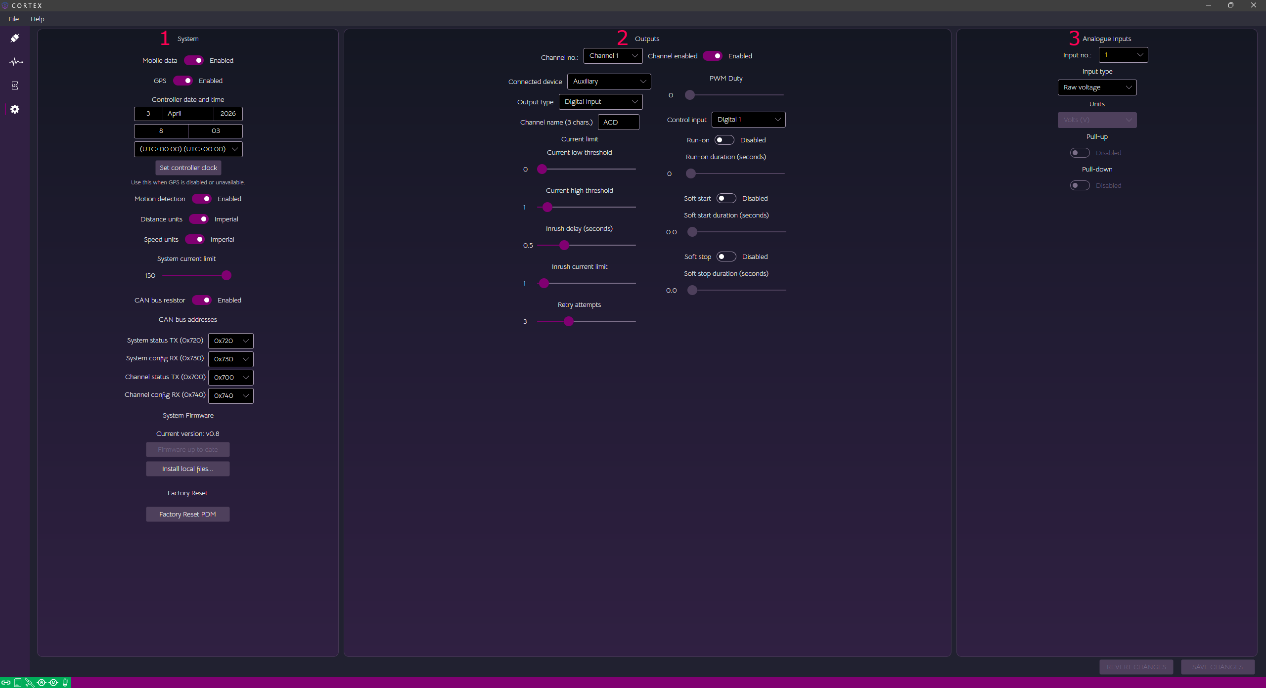
¶ 1. System Settings
- Mobile data - Enable or disable mobile data connections
- GPS - Enable or disable GPS
- Controller date and time - Manually set the controller date and time here in case GPS isn't used as the time source. Used for SD card logging internally and for time on the display.
- Controller timezone - Set the timezone. This writes daylight saving settings to the controller for automatic clock updates.
- Motion detection - Enable or disable motion detection while in sleep mode. This wakes the PDM when motion has been detected. Future updates will support tracking features.
- Distance units - Metric (kilometres) or imperial (miles)
- Speed units - Metric (kilometres) or imperial (miles)
- System current limit - This sets the total current limit for the PDM up to 150A
- CAN bus resistor - Enable or disable the internal CAN bus terminiation resistor
- CAN bss addresses - Allows you to set the various CAN bus addresses/message IDs. See the main Wiki page for CAN info.
- System Firmware - Here, the GitHub repo is checked for the latest release of firmware, if a newer version is available, Cortex can download and install it from here or you can browse to a .zip file containing the binary, SHA256 hash and the digital signature. Cortex will upload the firmware to the controller where it will verify the firmware and update itself using the built-in bootloader.
- Factory Reset - You can reset the controller to factory settings here.
¶ 2. Outputs
- Channel no. - Select which channel to change settings for.
- Enable - Permanently enable or disable this channel irrespective of settings.
- Connected device - This category determines the priority of the channel in a thermal shutdown scenario. Should the controller approach maximum operating temperature, low-priority channels are shut down to prevent thermal overload. This occurs in two stages,
temperature warning, andtemperature overload. - Output type:-
- Digital input - Simple, digital on or off channel which can be assigned either a digital input, or an analogue input configured as digital, either active high (pull-down enabled) or active low (pull-up enabled).
- Digital PWM - Fixed duty PWM output channel which can be assigned either a digital input, or an analogue input configured as digital, either active high (pull-down enabled) or active low (pull-up enabled).
- Digital intermittent - A fixed, slow duty on/off channel for components such as indicators. Configurable in 0.1s increments up to 10 seconds.
- Analogue - Threshold-based analogue input, digital output channel. This can work on either a postive-going or negative-going analogue input threshold with hysteresis. The assigned analogue input channel must be configured as an analogue input for this channel type to work correctly. The analogue input units are used in the threshold calculations.
- Scaled Analogue - Scaled analogue input, PWM output channel. This works as a scaled channel whereby the input scale and output PWM duty are linearly mapped. The analogue input units are used in the scaling.
- CAN Digital - CAN bus controlled, digital output channel.
- CAN PWM - CAN bus controlled, PWM output channel.
- Channel name - 3-character short name for the display.
- Current low threshold - Below this value, when the channel is enabled, the controller assumes the load is open-circuit. An energised output with a current reading below this value will trigger retry attempts. If retry attempts fail or are not configured, the channel will go into undercurrent lockout until the next disable/enable transition.
- Current high threshold - Above this value, when the channel is enabled, the controller assumes the load is overcurrent. An energised output with a current reading above this value will trigger retry attempts. If retry attempts fail or are not configured, the channel will go into overcurrent lockout until the next disable/enable transition.
- Inrush delay (seconds) - When the channel is enabled, the controller uses the inrush current limit for error checking. Once this time has expired, the normal current high threshold applies.
- Inrush current limt - This sets the inrush current limit during the above period up to 50A.
- Retry attempts - Number of retry attempts for this channel under over current or under current conditions.
- PWM duty - Sets the PWM duty for fixed PWM output channels.
- Control input - Sets the input used for this channel, for non-CAN enabled channels.
- Run-on - Enable or disable the run-on feature.
- Run-on duration (seconds) - With run-on enabled, if the channel is enabled at ignition off, the run-on feature will keep that output energised for the duration specified here. When that duration has elapsed, the channel will turn off and the controller will proceed to sleep mode as normal. This can be useful for cooling fans or electric coolant pumps etc.
- Soft start - Enable or disable the soft start feature.
- Soft start duration - At enable, the channel will ramp up PWM duty from zero to the configured PWM duty (for PWM-based channels) or to 100% duty for digital channels, over this period. This is used to enable inductive or capacitive loads where their inrush current can be many times the steady state current or as a means of reducing mechanical shock.
- Soft stop - Enable or disable the soft stop feature.
- Soft stop duration - At disable, the channel will ramp down PWM duty from the configured PWM duty (for PWM-based channels) or 100% duty for digital channels to zero, over this period. This is used to disable inductive or capacitive loads where their inductive kickback or overvoltage from mechanical inertia may damage the controller or as a means of reducing mechanical shock.
¶ 3. Analogue Inputs
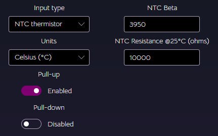
- Input type - Type of analogue input. Here you can configure the analogue input as raw voltage, digital, passive sensor, active sensor or NTC thermistor
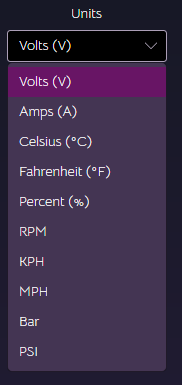
- Units - For passive sensors, active sensors and NTC thermistors, units can be selected.
- Pull-up - Enable or disable the 2.49K pull-up resistor for this input.
- Pull-down - Enable or disable the 2.49K pull-down resistor for this input.
¶ Analogue input units
Currently supported units:
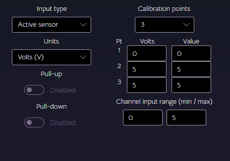
¶ Active & passive sensor inputs
Active and passive sensors can be calibrated using 2 or 3 point calibration. 2 point calibration for simple, linear scaling. 3 point calibration calculates a best-fit curve.
Pull-up and pull-down resistors are disabled for active sensors.
Either pull-up or pull-down can be enabled for passive sensors.
¶ NTC thermistor input
An NTC thermistor can be configured high side or low side (supplied by 5V or grounded). You will need to know the beta value and nominal resitance at 25°C.
¶ 4. Revert and Save
Once changes have been made to the settings, these buttons will be enabled. This alerts the user that pending controller changes are present. You can either revert to the current state of the controller or save the changes to the controller.
Saving will take longer, the more channels are active. This is because more current readings are being taken for each enabled channel.
¶ 5. Last Update Time
When the controller receives an update, the last update date and time will show here. Update actions are also logged to the system log.