WBO2 is an open-source, wideband O2 controller for use with Bosch LSU 4.x sensors. Based on the Bosch CJ125 chip and an ATTiny1614 microcontroller, it uses modified source code from Bylund Automotive's Arduino based project.
Update March 2024. HW v1.3 & FW v1.1.0 released. Analogue output now correctly scaled.
¶ Specifications
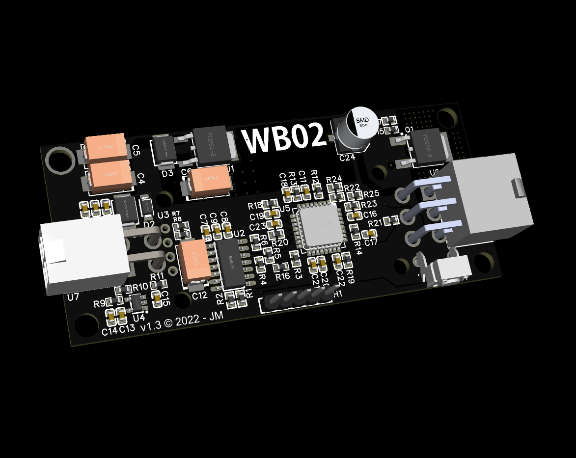
The PCB measures 80x35mm. Schematics and PCB layout can be found here.
- Lambda measurement range 0.67 to ∞ (air)
- 0 to 5V true analogue output (Effective 12.1 to 18.1 AFR, petrol)
- Sensor warm-up phase as specified by Bosch
- PID heater control
- 7-segment display
- Heater cut-out in case of error
¶ PCB Assembly
Most of the components on the PCB are SMD, 0603 size. While these are very small, they are still manageable for DIY assembly. There are hundreds of videos online showing various techniques. Alternatively, boards can be ordered populated with surface mount components provided the BOM and pick and place files are correct. JLC PCB offer this service at very reasonable prices and ship to most countries.
¶ Board Revision
The current board revision is v1.3. This improves on the first design by using more filtering on the supply with a linear regulator. The output is goes through a low-pass filter and is scaled through an op-amp to 0-5V instead of 0-4.3V.
Firmware v1.0.6 supports v1.3 hardware. Backward compatibility is not maintained.
LEDs have been replaced with a 7-segment display module which is optional. Larger Molex connectors and mounting holes are present and the PCB features a better low-noise and thermal design.
Note the pin assignment is different on the larger Molex connectors from v1.1.
¶ Sensor Measurement
The CJ125 measures the oxygen concentration by means of measuring the pump current () in the sensor. The changes with the O2 concentration. In turn, the CJ125 amplifies this signal which is read by the microcontroller.
The CJ125 has two selectable amplification ranges for lean or rich applications. These are defined as for lean, and for rich.
In the Bosch datasheet for the LSU 4.9 wideband sensor is a table that gives us measured , Lambda (λ) and the output voltage of an evaluation circuit for both ranges.
| Ip [mA] | Lambda (λ) value | Ua [V], v=17 | Ua [V], v=8 |
|---|---|---|---|
| -2 | 0.65 | 0.51 | |
| -1.602 | 0.7 | 0.707 | |
| -1.243 | 0.75 | 0.192 | 0.884 |
| -0.927 | 0.8 | 0.525 | 1.041 |
| -0.8 | 0.822 | 0.658 | 1.104 |
| -0.652 | 0.85 | 0.814 | 1.177 |
| -0.405 | 0.9 | 1.074 | 1.299 |
| -0.183 | 0.95 | 1.307 | 1.409 |
| -0.106 | 0.97 | 1.388 | 1.448 |
| -0.04 | 0.99 | 1.458 | 1.48 |
| 0 | 1.003 | 1.5 | 1.5 |
| 0.015 | 1.01 | 1.515 | 1.507 |
| 0.097 | 1.05 | 1.602 | 1.548 |
| 0.193 | 1.1 | 1.703 | 1.596 |
| 0.25 | 1.132 | 1.763 | 1.624 |
| 0.329 | 1.179 | 1.846 | 1.663 |
| 0.671 | 1.429 | 2.206 | 1.832 |
| 0.938 | 1.701 | 2.487 | 1.964 |
| 1.15 | 1.99 | 2.71 | 2.069 |
| 1.385 | 2.434 | 2.958 | 2.186 |
| 1.7 | 3.413 | 3.289 | 2.342 |
| 2 | 5.391 | 3.605 | 2.49 |
| 2.15 | 7.506 | 3.762 | 2.565 |
| 2.25 | 10.119 | 3.868 | 2.614 |
To confirm that this evaluation circuit is using a CJ125, we can use the formula described in the Bosch Technical Product Information datasheet, 258 E00 015e:
Where is the selected amplification range, or .
Taking an example of -0.405mA from the table above, we can confim that the result matches that of the value for the lean () range:
Now we know the voltage given by the example circuit matches what we would expect to see from the CJ125. We can calculate the expected 10-bit ADC value, using the example of 1.074V:
These values produce the following results:
| Lambda (λ) value | Ua [V], v=17 | ADC Value |
|---|---|---|
| 0.65 | ||
| 0.7 | ||
| 0.75 | 0.192 | 39 |
| 0.8 | 0.525 | 107 |
| 0.822 | 0.658 | 135 |
| 0.85 | 0.814 | 167 |
| 0.9 | 1.074 | 220 |
| 0.95 | 1.307 | 267 |
| 0.97 | 1.388 | 284 |
| 0.99 | 1.458 | 298 |
| 1.003 | 1.5 | 307 |
| 1.01 | 1.515 | 310 |
| 1.05 | 1.602 | 328 |
| 1.1 | 1.703 | 348 |
| 1.132 | 1.763 | 361 |
| 1.179 | 1.846 | 378 |
| 1.429 | 2.206 | 451 |
| 1.701 | 2.487 | 509 |
| 1.99 | 2.71 | 554 |
| 2.434 | 2.958 | 605 |
| 3.413 | 3.289 | 673 |
| 5.391 | 3.605 | 738 |
| 7.506 | 3.762 | 770 |
| 10.119 | 3.868 | 791 |
In the Bylund Automotive code, the Lambda value is obtained by means of a lookup table which closely resembles the results above. This is much more practical and much faster than calculating the Lambda for an 8-bit AVR which only has floating point precision of 6-7 digits. The full range of measurement gives us the following values:
| Input ADC Value | Lambda (λ) value | AFR (Petrol) |
|---|---|---|
| 39 | 0.750 | 11.03 |
| 791 | 10.119 | 148.75 |
Now we can see that it isn't practical to output the entire measureable Lambda range on the analogue output.
From FW v1.1.0, WBO2 outputs 0 to 5V for a range of 12.1 to 18.1 AFR meaning for a Lambda value of 1 (AFR 14.7) is 2.18V.
¶ Mode of Operation
The controller completes a warm-up phase specified by the Bosch datasheet at power-up. This warm-up phase helps prolong the life of the sensor by reducing thermal shock.
During this phase, the controller outputs two calibration voltages, first 2.18V (14.7 AFR) for the duration of the condensation phase (5 seconds) which is equivalent to a Lambda of 1.0 or 14.7:1 AFR (petrol). Secondly, 4.95V for the remaining warm-up phase which is equivalent to a Lambda of 1.22 or 18.0:1 AFR (petrol). This provides two calibration points for a connected ECU at start-up.
The controller follows this sequence at power up:
¶ Display
Starting from hardware v1.1, a 4x7 digit LED display is fitted supported by firmware v1.0.5.
At power up, the display shows the current firmware version then displays the two calibration values shown above (AFR).
Once the condensation and warm up phases are complete, the display shows the current AFR value which is derived from the analogue output value.
Should an error occur, this will be displayed.
¶ Connections
The 4-pin connector has two ground pins to provide a convinient location for shielded cable if required. Pin-out as follows:
| Molex Pin | Function |
|---|---|
| 1 | 0 to 5V analogue output (A0) |
| 2 | +12V |
| 3 | GND |
| 4 | GND |
The 6-pin connector is for the O2 sensor. Bosch LSU 4.x sensors are supported.
Note this pin assignment is valid for PCB version 1.1 upwards.
| Molex/PCB Pin | LSU 4.9 | LSU 4.2 | Function |
|---|---|---|---|
| 1 | 3 | 4 | Heater voltage H- / Uh |
| 2 | 1 | 1 | Pump current APE / IP |
| 3 | 5 | 6 | Trim resistor RT / IA |
| 4 | 4 | 5 | Heater voltage H+ / Uh+ |
| 5 | 2 | 3 | Virtual ground IPN / VM |
| 6 | 6 | 2 | Nernst voltage UN / RE |
¶ Environmental Protection
Typically, the board may be mounted in the engine bay. Somewhere which exposes it to temperature and humidity changes. I recommend using high temperature conformal coating and heat shrink to protect it or find a suitable enclosure.
¶ Programming
The ATTiny1614 chip uses a very simple, 3-pin, UPDI (Unified Programming and Debug Interface).
The easiest way to program it is by using the megaTinyCore Arduino core with the Arduino IDE. It's worth reading through the documentation there and understanding how to build a programmer.
The source code is available over on my GitHub page.
¶ Licensing & Open Source
WBO2 is open source and has been developed with DIY enthusiasts in mind.
Wideband O2 Controller by Joe Mann is licensed under CC BY-NC-SA 4.0![]()
![]()
![]()
![]()