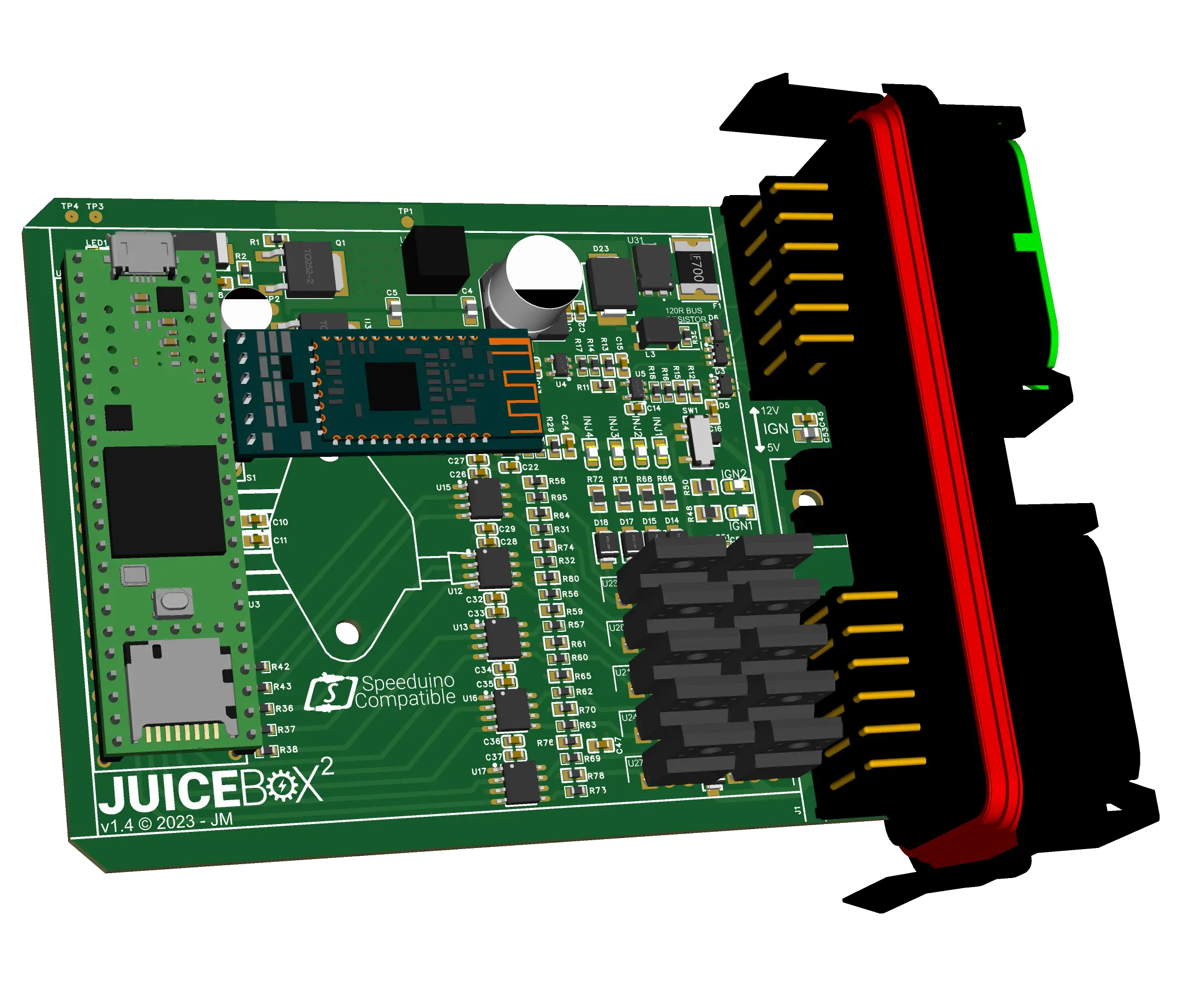
Juice Box 2 is an open-source, engine management ECU designed around the Speeduino project. Designed with robustness in mind for the DIY/enthusiast.
¶ Specifications
The PCB is designed to fit in the Amphenol IPX or Deutsch PCB enclosures.
Note that a vented enclosure should be selected to maintain accuracy of the MAP sensor value.
Due to component shortages around 2020 - 2023, I decided to develop another version based on the same IO, but using components with much more common footprints. I also removed the expensive and difficult to obtain isolated devices. This version can be found here: Open Source Hardware Lab.
All the following details describe the latest, non-isolated version of the board.
Features:
- Teensy 3.5 microcontroller
- Fully sealed Deutsch enclosure & connectors
- Support for 1-4 cylinders, wasted spark, sequential injection
- Supports 36-1, 60-2 and other trigger wheel types
- Crank and Cam angle sensor inputs (Hall effect compatible)
- On-board MAP sensor
- 5 analogue inputs for O2, inlet air temperature, throttle position, coolant temperature and 1 auxiliary
- Cooling fan and fuel pump outputs
- Built-in CAN which also supports OBD II
- Sensor calibration
- 16 x 16 ignition table
- Data logging
- USB
- Bluetooth
¶ PCB Assembly
Most of the components on the PCB are SMD, 0603 size. While these are very small, they are still manageable for DIY assembly. There are hundreds of videos online showing various techniques. Alternatively, boards can be ordered populated with surface mount components provided the BOM and pick and place files are correct. JLC PCB offer this service at very reasonable prices and ship to most countries.
¶ Test Points
The board has 4 test points. Note the correct ground reference when using these (IO or processor side ground).
| Test Point | Function |
|---|---|
| 1 | 12V supply, filtered |
| 2 | 12V supply, after capacitance multiplier |
| 3 | 5V supply |
| 4 | Ground |
¶ Board Revision
Current version of the board is v1.4. This version removes galvanic isolation (component availability and cost) and uses much more commonly available components.
¶ Connections
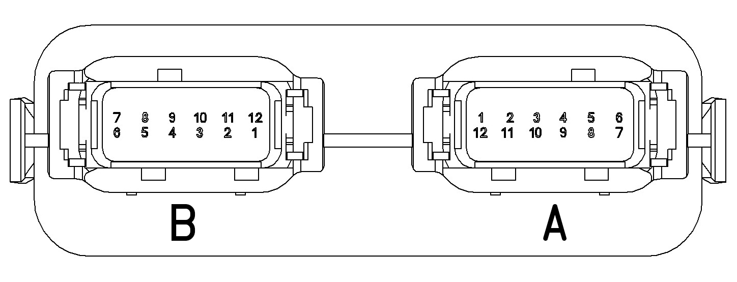
2 x 12 way DTM connector. Looking at the connector end on, the 'B' connector is on the left, the 'A' connector on the right.
| DTM 'B' Pin | Teensy Pin | Function | DTM 'A' Pin | Teensy Pin | Function |
|---|---|---|---|---|---|
| 1 | 39 | Ignition coil 1 output (IGN1) | 1 | N/A | 5V analogue reference output (5VREF) |
| 2 | 37 | Injector 1 output (INJ1) | 2 | A4 | O2 sensor input (O2) |
| 3 | 35 | Injector 3 output (INJ3) | 3 | A5 | Auxiliary sensor 1 input (AUX1) |
| 4 | 33 | Fuel pump output (FPO) | 4 | 3/4 | CAN bus low (CANL) |
| 5 | 27 | Tacho output (TACH) | 5 | 23 | Camhsaft position sensor (CAM) |
| 6 | 29 | PWM 1 out (PMW1) | 6 | N/A | 12V input (+VE) |
| 7 | 30 | PWM 2 out (PMW2) | 7 | GND | Ground (GND) |
| 8 | 28 | High-current output 1 (HC1) | 8 | 22 | Crankshaft position sensor (CRK) |
| 9 | 26 | Cooling fan output (CFO) | 9 | 3/4 | CAN bus high (CANH) |
| 10 | 34 | Injector 4 output (INJ4) | 10 | A2 | Inlet air temperature (IAT) |
| 11 | 36 | Injector 2 output (INJ2) | 11 | A3 | Coolant temperature input (CLT) |
| 12 | 38 | Ignition coil 2 output (IGN2) | 12 | A1 | Throttle position sensor input (TPS) |
The MAP sensor used is the MPX4250 which has a 5mm barb. Most 6mm OD tubing will fit. The bulkhead adaptor used on the board shown is a 4mm push fit adaptor which screws into an M12x1 thread tapped into the connector housing.
¶ Wiring
I recommend taking some time to read through the Speeduino wiki since most of the relevant wiring is identical to Juice Box (observing the pin-out above). A few notes on the other inputs and outputs:
¶ Auxiliary analogue inputs
These can be used like any of the other analogue inputs. Either a 2-wire (signal and ground) or 3-wire (5V reference, signal and ground) can be used.
¶ High current, fan, PWM and fuel pump outputs
These 4 outputs are sinking which means one side of the device you are trying to switch is connected to the positive supply, the other is connected to the output pin on Juice Box. When the output is enabled, the pin is connected to ground, completing the circuit to the device. High current outputs are capable of switching 2 amps. If you need to switch more or need to switch the positive side of a device, a relay can be added to the circuit.
¶ Tachometer output
The tachometer output is a 12V signal pulsed for each spark event (2 per revolution on a 4 cylinder, wasted spark configuration).
¶ LED Indicators
| LED Label | Meaning |
|---|---|
| LED1 | Power on |
| IGN1-2 | Ignition outputs |
| INJ1-4 | Injector outputs |
¶ Basic 4-cylinder example
¶ Configuration
Configuration is via TunerStudio. Tuner Studio is a fully-featured EFI analytics and tuning application but is compatible with Juice Box for configuring ignition and sensor settings. Refer to the Speeduino Wiki pages for more detailed information on configuring TunerStudio.
Mobile apps such as Shadow Dash and Real Dash offer Bluetooth connectivity via mobile for logging. MSDroid can be connected for full functionality via an OTG USB cable.
¶ Bluetooth Module
The PCB accepts an HC-05 Bluetooth plug-in module. Before a new HC-05 module can be used, it must be programmed with a baud rate of 38400. The easiest way to program a module is to assemble the board and use the Teensy to program it.
- Power down controller
- Hold the key button down on the Bluetooth module, power up the controller
- Flash this Arduino sketch to the Teensy:
#include <SoftwareSerial.h>

SoftwareSerial mySerial(9, 10); // RX, TX

void setup()
{
  Serial.begin(9600); // Serial monitor

  mySerial.begin(9600); // Bluetooth module (38400 for programming mode if using an HC-05)
}

void loop()
{

  if (mySerial.available())
  {
  	Serial.write(mySerial.read());
  }

  if (Serial.available())
    {
  	mySerial.write(Serial.read());
    }
}
- Open the serial monitor in the Arduino IDE
- Enter
ATand the HC-05 should respond withOK - Now enter
AT+UART=115200,0,0to set the baud rate to 115200, the stop bit to 0 (1-bit) and the parity to 0 (none) - The name can be set with
AT+NAME=and the password withAT+PSWD= - Now the HC-05 module is configured.
- Power down the controller and set the BT-PRGM switch to the "OFF" position
- Flash the Speeduino firmware to the Teensy
- Connect to TunerStudio and configure the second serial under Accessories -> Secondary Serial IO Interface
- You should be able to connect to the Juice Box using Real Dash or Shadow Dash
For more information on the HC-05 module, see this PDF
¶ Licensing & Open Source
Juice Box 2 is open source and has been developed with DIY enthusiasts in mind. It is available for anyone to duplicate or modify according to the GPL 3.0 license. Juice Box 2 is not officially affiliated or endorsed by the creators of the Speeduino project.